










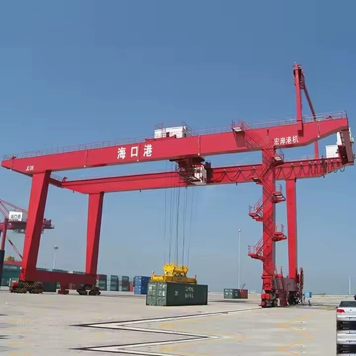


Rail-Mounted Gantry (RMG) Cranes
Products Description
Key Features & Advantages
High-Density Stacking Capacity
Typically stack containers 6-8 high (up to 1-over-7 configuration)
Can span up to 12 container rows wide
Enable 50-60% more storage capacity than RTG systems
Precision Handling
±5mm positioning accuracy
Anti-sway control systems
Dual-lift capability (twin 20' containers)
Energy Efficiency
Regenerative braking systems recover 20-30% of energy
Full electric operation (no diesel emissions)
Average power consumption: 25-35 kWh per move
Automation Readiness
Pre-equipped for automated operation
Compatible with optical character recognition (OCR) systems
Integration with terminal operating systems (TOS)
Operational Reliability
98-99% mechanical availability
Designed for 24/7 operation
30+ year service life with proper maintenance
Comparison with RTG Cranes
| Feature | RMG Cranes | RTG Cranes |
|---|---|---|
| Mobility | Fixed rail tracks | Rubber tires |
| Stack Height | Higher (6-8 containers) | Lower (4-5 containers) |
| Energy Source | Electric only | Diesel/electric |
| Automation | Fully automatable | Limited automation |
| Footprint | Smaller (higher density) | Larger |
| Initial Cost | Higher | Lower |
| Operating Cost | Lower | Higher |
Parameter Typical Range
Span 30-50 meters
Lifting Height 15-25 meters
Lifting Capacity 40-60 tons
Trolley Speed 120-180 m/min
Gantry Speed 60-120 m/min
Hoisting Speed 30-60 m/min
Power Supply 480V-690V AC
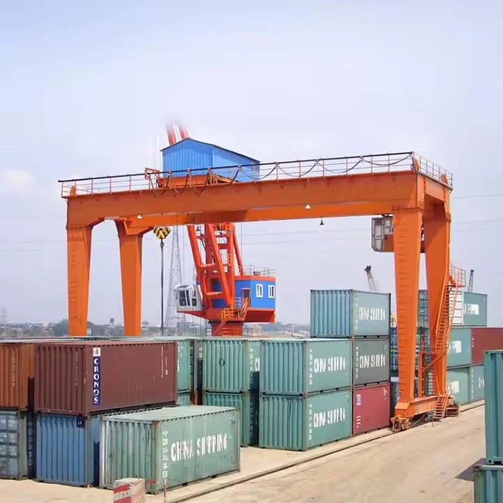
Pictures & Components
Rail-Mounted Gantry (RMG) Cranes: Components Breakdown
Rail-Mounted Gantry (RMG) cranes consist of sophisticated mechanical, electrical, and structural systems working in unison to handle container stacking and transport operations efficiently. Below is a detailed technical breakdown of their key components:
1. Structural Components
A. Gantry Frame
Portal Beams: Horizontal structural members spanning the container stack width (typically 30-50m)
Leg Assemblies: Vertical supports with reinforced steel construction
Cross Braces: Diagonal members providing torsional stability
Bogie Connection Points: Heavy-duty interfaces with rail bogies

B. Boom/Lifting Beam
Main Girder: Box-type steel construction for rigidity
Trolley Rails: Precision-machined tracks for smooth trolley movement
End Trucks: Wheel assemblies at boom extremities
C. Rail System
Running Rails: Heavy-duty AS60/AS68 rails (60kg/m or 68kg/m profile)
Rail Clamps: Automatic locking devices for parking
Rail Sweepers: Debris-clearing mechanisms
Alignment Systems: Laser-guided rail position monitoring
 |
 |
2. Motion Systems
A. Gantry Travel System
Drive Bogies: Powered wheel assemblies (4-8 units per crane)
AC Vector Motors: 30-75kW per drive (regenerative capable)
Frequency Converters: For smooth acceleration/deceleration
Rail Wheels: Forged steel wheels with hardened treads
B. Trolley System
Drive Mechanism: AC motors with gear reducers
Trolley Wheels: Polyurethane or steel wheels with flanges
Position Encoders: Absolute encoders (±2mm accuracy)
Anti-Sway System: Active load control algorithms
C. Hoisting System
Drum Hoists: 2-4 grooved drums with wire rope spooling
Wire Ropes: Rotation-resistant 18-28mm diameter
Sheave Assemblies: Precision-aligned pulley systems
Load Cells: Strain-gauge based (0.5% accuracy)
 |
 |
3. Lifting & Handling Components
A. Spreader Assembly
Frame Structure: Telescopic or fixed design
Twistlocks: Hydraulic or electromechanical actuators
Guide Arms: Container positioning aids
Weighing System: Integrated load measurement
B. Auxiliary Lifting Devices
Reefer Plugs: Power connections for refrigerated containers
Camera Systems: 4-6 HD cameras for remote operation
Laser Scanners: Container position verification

4. Electrical Systems
A. Power Distribution
Collector Beams: Pantograph or sliding shoe systems
Main Switchgear: 400-690V AC distribution
Transformer: Step-down for control circuits
Emergency Generator: Backup power source
B. Control Systems
PLC Controller: Redundant safety PLCs (SIL-2/SIL-3)
HMI Panels: Touchscreen interfaces
Remote I/O Stations: Distributed field devices
Communication Network: PROFIBUS/ETHERNET IP
C. Drive Systems
AC Drives: Regenerative capability
Braking Resistors: Dynamic braking systems
Soft Starters: For auxiliary motors

5. Safety Systems
A. Mechanical Safeguards
Anemometer: Wind speed monitoring (auto-stop >20m/s)
Anti-Collision: Laser/radar-based systems
Overload Protection: Multiple redundant systems
Emergency Stop: Category 0 stop circuits
B. Electrical Protections
Ground Fault Monitoring
Phase Sequence Protection
Overvoltage/Undervoltage
Motor Thermal Protection
C. Operational Safety
Access Platforms: With safety gates
Warning Lights: Rotating beacons
Audible Alarms: 105dB horns
E-Stop Stations: Strategically located

.
6. Automation Components (for Automated RMGs)
A. Navigation Systems
Laser Positioning: ±5mm accuracy
RFID Readers: Container identification
OCR Cameras: Container code recognition
B. Control Infrastructure
Equipment Controller: Dedicated automation PLC
Wireless APs: 5GHz mesh network
Traffic Management: Path planning algorithms
C. Monitoring Systems
Vibration Sensors: Bearing condition monitoring
Thermal Cameras: Electrical component monitoring
Oil Analysis: Gearbox health monitoring

7. Ancillary Systems
A. Maintenance Features
Lubrication Systems: Automatic greasing
Access Platforms: Full perimeter access
Service Cranes: For component replacement
B. Environmental Protection
Corrosion Protection: ISO 12944 C5-M coating
Lightning Protection: Full Faraday cage design
Heating Elements: For cold climate operation
C. Operator Interfaces
Local Control Cabin: (For manned operation)
Remote Operation Station: Dual-screen setup
VR Training Simulator: For operator training

SKETCH

Main technical

Advantages
Space Optimization
Achieve 40-50% higher stacking density than RTG systems
Typical configuration: 1-over-6 or 1-over-7 container stacks
Can operate in narrow corridors (as little as 18m wide)
Operational Efficiency
Handling capacity: 25-35 moves/hour (up to 50 in automated systems)
Simultaneous trolley and gantry movement
Fast cycle times (90-120 seconds per move)
Energy Efficiency
100% electric operation (zero onsite emissions)
Regenerative braking recovers 20-30% of energy
Average consumption: 0.8-1.2 kWh per container move
Precision Handling
±5mm positioning accuracy
Advanced anti-sway control systems
Dual-lift capability (twin 20' containers)
Automation Readiness
Native compatibility with terminal operating systems (TOS)
Pre-engineered for full automation
Integrated container recognition systems (OCR, RFID)
Low Lifetime Costs
30+ year service life
98-99% mechanical availability
Reduced manpower requirements
Environmental Benefits
Noise levels below 75 dB(A)
No local emissions
Minimal light pollution (automated systems)
Application
Primary Applications
Container Terminal Operations
High-density yard stacking (6-8 containers high)
Intermodal transfer operations
Buffer storage for peak periods
Automated Container Terminals
Core equipment in automated storage blocks
Interface with automated guided vehicles (AGVs)
Integration with automated stacking cranes (ASCs)
Intermodal Facilities
Rail terminal operations
Barge terminal operations
Cross-dock facilities
Specialized Cargo Handling
Reefer container parks with power connections
Dangerous goods storage areas
Out-of-gauge cargo handling
Port Expansion Projects
Maximizing throughput in land-constrained ports
Greenfield terminal developments
Brownfield automation upgrades
Emerging Applications
Smart Port Initiatives
Digital twin integration
AI-powered traffic optimization
Predictive maintenance systems
Cold Chain Logistics
Automated reefer container management
Temperature-monitored storage
Priority handling systems
Sustainable Ports
Solar-powered RMG operations
Energy-neutral container blocks
Carbon footprint reduction programs
Urban Logistics Hubs
Compact container storage solutions
Noise-controlled nighttime operations
Multi-level stacking configurations
Comparison with Alternative Systems
Crane production procedure
1. Design and Engineering
Blueprint and Structural Design: Engineering teams design the crane based on specifications, considering the weight, span, lifting capacity, and working environment.
Component Specifications: Detailed specifications for components such as the main girders, end beams, hoist system, trolley, and electrical components are prepared.
2. Material Selection and Procurement
Steel Material Selection: High-strength steel materials are chosen for the main girders, columns, and other critical parts.
Procurement: Materials, such as steel plates, sections, bolts, and electrical components, are sourced and inspected for quality.
3. Cutting and Pre-Fabrication
Cutting and Shaping: Steel components are cut, shaped, and welded into preliminary forms according to the design specifications.
Pre-Fabrication Assembly: Components such as beams and girders are pre-assembled to verify that they fit together properly.
4. Welding and Structural Assembly
Welding: Main girders, columns, and other structural components are welded to create a sturdy framework. Specialized welding techniques are used to ensure strength and durability.
Structural Assembly: The main girders and end beams are assembled, ensuring precise alignment for balanced load distribution.
Quality Control: Welding seams and joints are inspected using non-destructive testing (e.g., ultrasonic or X-ray testing) for any structural defects.
5. Machining and Finishing
Machining of Parts: Critical parts such as the wheels, trolley components, and hoists undergo machining for proper fitting and smooth operation.
Surface Treatment: Steel parts are cleaned and subjected to surface treatments like sandblasting and coating to prevent rust and enhance durability.
Painting and Coating: Protective coatings are applied for weather resistance, with a primer followed by top coats.
6. Assembly of Crane Components
Main Girder Assembly: The two main girders are mounted and aligned.
End Beam Installation: End beams are fixed to the main girders, forming the frame of the crane.
Hoist and Trolley Installation: The hoist mechanism and trolley are mounted on the main girder rails and tested for alignment and operational smoothness.
7. Electrical and Control Systems Installation
Wiring and Cabling: Electrical wiring is installed for power supply, control circuits, and safety systems.
Control Panel and Safety Features: The control panel is mounted, with safety features such as limit switches, emergency stops, and overload protection integrated and tested.
Control System Programming: The crane's control system is programmed and tested for correct operation.
8. Testing and Quality Assurance
Load Testing: The crane is subjected to load tests to ensure it can handle its rated capacity without issues.
Operational Testing: Functional tests are performed to check movements, responsiveness, braking systems, and electrical operations.
Inspection and Certification: The crane undergoes final inspections to verify compliance with safety regulations and standards. Certification may be issued by relevant authorities.
9. Final Adjustments and Delivery Preparation
Final Adjustments: Any minor adjustments are made to ensure smooth operation.
Documentation: Operation manuals, maintenance guidelines, and certification documents are prepared for delivery.
Packaging and Shipping: The crane is packaged securely for shipment, ensuring all parts are protected during transit.
10. Installation and Commissioning (at Site)
On-site Assembly: The crane is assembled at the customer's location if required.

Workshop view:
The company has installed an intelligent equipment management platform, and has installed 310 sets (sets) of handling and welding robots. After the completion of the plan, there will be more than 500 sets (sets), and the equipment networking rate will reach 95%. 32 welding lines have been put into use, 50 are planned to be installed, and the automation rate of the entire product line has reached 85%.


Hot Tags: rail-mounted gantry (rmg) cranes, China rail-mounted gantry (rmg) cranes manufacturers, suppliers, factory
You Might Also Like




Send Inquiry