










Container Rail Mounted Gantry Crane
Products Description
What is a Container RMG?
It is a large, electrically-powered gantry crane that runs on a fixed track or rail system. Its defining feature is the use of a spreader, a specialized lifting attachment that locks onto the corner castings of a container for secure and fast handling.
Primary Function: To stack containers in dense blocks, moving them from a transport vehicle (like a truck or train) to a storage location, and vice versa.
Key Advantages of Container RMGs
High Storage Density: They can stack containers many rows wide (typically 6-10 containers) and several tiers high (often 4-6 containers "over-1"), maximizing the use of valuable yard space.
High Productivity and Efficiency: Designed for rapid cycling, moving containers quickly between trucks, trains, and storage blocks.
Precision Handling: The rail-guided movement and sophisticated controls allow for very accurate container placement, which is essential for high-density stacking.
Zero Local Emissions: Being all-electric, they produce no exhaust emissions, making them ideal for environmentally sensitive areas.
Low Operating Costs: Electricity is cheaper than diesel, and electric motors require less maintenance than diesel engines, leading to lower lifetime costs.
Excellent for Automation: The fixed path and precise control make RMGs the ideal platform for automation, which reduces labor costs and improves safety and consistency.
Comparison with Other Container Handling Cranes
| Feature | Container RMG | Rubber-Tired Gantry (RTG) | Reach Stacker |
|---|---|---|---|
| Mobility | Fixed to rails. Moves only lengthwise. | Highly mobile on rubber tires. Can change lanes. | Very mobile, like a large forklift. |
| Storage Density | Very High (Many rows wide) | Medium (Typically 6+1 rows wide) | Low (Typically 2-3 containers deep) |
| Environmental Impact | Zero emissions, quiet. | Diesel engine produces emissions and noise. | Diesel engine produces emissions and noise. |
| Automation | Excellent. The standard for automation. | Possible, but more complex. | Rare. Mostly manual. |
| Cost | High initial infrastructure cost. Lower operating cost. | Lower initial cost. Higher operating cost (fuel, tires). | Lower initial cost. Higher operating cost. |
| Best For | High-volume, fixed-layout terminals requiring high density and automation. | Flexible terminals with changing layouts or medium volume. | Small terminals, depots, or supplemental handling in large yards. |
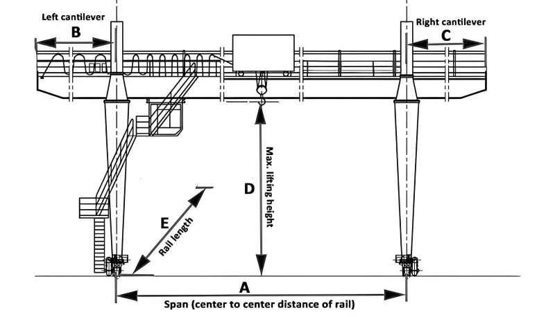
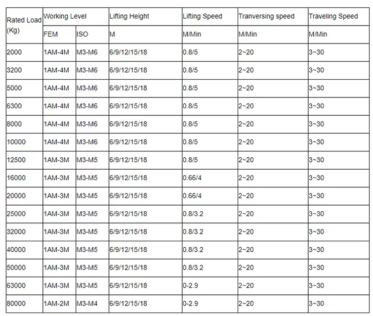
Lifting Capacity 320 tons
Span (Width) 3 - 12 meters (adjustable)
Lifting Height 3 - 10 meters
Working Class A3-A5 (light to medium duty)
Hoisting Speed 0.5 - 8 m/min (variable)
Main Beam Type Single/double girder (box-type)
Power Supply 220V/380V 3-phase or manual
Control Mode Pendant control/wireless remote
Hoist Type Electric chain hoist/wire rope hoist
Travel Drive Manual push or motorized
Corrosion Protection Hot-dip galvanized or marine-grade paint
Wind Resistance Up to Beaufort scale 6 (for outdoor use)
Operating Temp -20°C to +50°C

Pictures & Components
A Container Rail Mounted Gantry Crane (RMG) is a complex system composed of several major components that work together to handle containers with precision and efficiency.
Here is a detailed breakdown of its key components, categorized by system:
1. Main Structural Components (The Skeleton)
These components form the primary framework of the crane, supporting all other parts and the load itself.
Main Girder(s) / Bridge: The primary horizontal beam that spans the width of the container stack. In a container RMG, this is almost always a double girder design for the strength required to handle heavy containers (40+ tons) and support the trolley.
End Carriages / Legs: The vertical structures at each end of the main girder. They house the wheels and drive mechanisms that allow the crane to travel along the runway rails.
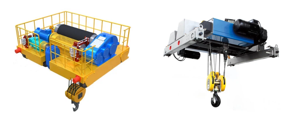
Trolley Frame: The structure that moves back and forth (traverses) along the main girder(s). It carries the hoist unit and the spreader.
2. Lifting and Handling Components (The Muscles)
This system is responsible for actually gripping, lifting, and moving the containers.
Spreader: The most critical component for container handling. It is a specialized frame that:
Locks Onto Containers: Uses twistlocks that automatically engage and disengage from the container's corner castings.
Telescopes: Can adjust its length to handle different container sizes (20ft, 40ft, 45ft).
Special Functions: Can be equipped for twin-lift (lifting two 20ft containers at once) or have a rotator to skew a container for precise placement.
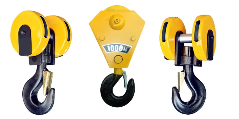
Hoist Unit: The winch mechanism that lifts and lowers the spreader and container. It consists of a powerful electric motor, a gearbox, a drum wrapped with wire rope, and high-capacity brakes.
Rope Sheaves: Pulleys that guide the wire rope from the hoist drum down to the spreader.

3. Motion and Drive Components (The Locomotion)
These components enable the crane to move in all three required directions.
Gantry Travel System (Long Travel):
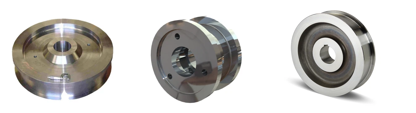
Wheels & Bogies: Sets of wheels mounted on the end carriages. Large RMGs use bogie assemblies with multiple wheels to distribute the immense weight.
Travel Drive Motors: Electric motors that power the wheels to move the entire crane forward and backward along the runway rails.
Trolley Drive System (Traverse Travel):
Trolley Wheels: Wheels that run on rails mounted on the top of the main girders.
Trolley Drive Motor: The motor that moves the trolley (and the suspended container) horizontally across the width of the crane.
Variable Frequency Drives (VFDs): Electronic devices that control the speed and torque of the hoist, trolley, and gantry motors. They are essential for providing smooth, controlled acceleration and deceleration, which is critical for precise positioning and preventing container swing.
4. Electrical and Power Systems (The Nerves and Energy)
This system provides power and control signals to the entire crane.
Power Delivery System:
Conductor Bar (Busbar): Insulated electrical bars running parallel to the crane runway. Collector shoes on the crane slide along these bars to bring continuous electrical power to the crane.
Control System:
Programmable Logic Controller (PLC): The "brain" of the crane. It processes commands from the operator and signals from sensors to control all crane movements and safety functions.
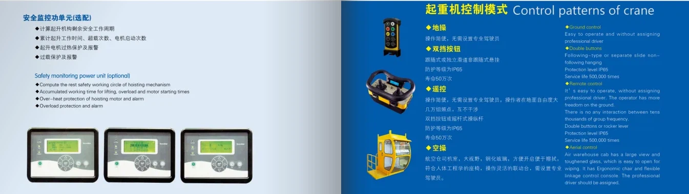
Operator's Cab / Remote Control: The interface for the operator. It can be a climate-controlled cab mounted on the trolley (for optimal visibility) or a portable radio remote control unit allowing operation from the ground.
Human-Machine Interface (HMI): A touchscreen display in the cab or on the remote control that shows vital information like load weight, crane position, diagnostics, and fault messages.
Cable Reels: For cranes with auxiliary functions or those using a cable reel for main power (less common than busbars for large RMGs), these reels pay out and retract cables neatly as the crane moves.

5. Safety and Sensor Systems (The Reflexes)
These components protect the crane, the container, and personnel.
Load Moment Indicator (LMI) System: A critical safety system that includes a load cell to measure the weight of the container and prevent the crane from being overloaded.
Anemometer: A wind speed sensor mounted high on the crane. It provides data to the PLC, which will trigger alarms and automatically slow or stop crane operations if wind speeds exceed safe limits.
Anti-Collision System: Uses laser scanners, radar, or GPS to detect obstacles, other cranes, or personnel and automatically stops movement to prevent collisions.

Limit Switches & Encoders:
Limit Switches: Hardwired safety devices that cut power at the extreme ends of travel for the hoist (upper/lower limit) and trolley.
Encoders: High-precision sensors that provide real-time feedback to the PLC on the position and speed of the hoist, trolley, and gantry.
Positioning Systems: Absolute Positioning Systems using lasers or GPS allow the crane to know its exact location in the yard down to the millimeter, which is essential for automation.
Emergency Stop (E-Stop) Buttons: Located at multiple points on the crane and on the remote control to allow for immediate shutdown in case of an emergency.

6. Runway System (The Foundation)
This is the fixed infrastructure on which the crane operates.
Runway Rails: Heavy-duty steel rails installed on a massive concrete foundation. The precise alignment and levelness of these rails are critical for the smooth and safe operation of the crane.
SKETCH
Main technical
Advantages
Advantages of Container RMGs
Container RMGs offer a powerful combination of operational, economic, and environmental benefits that make them the preferred choice for high-volume terminals.
1. Operational Advantages
High Storage Density: This is their primary advantage. RMGs run on fixed rails, allowing them to span and service many container rows wide (typically 6 to 10+) and stack containers several tiers high (often 4 to 6 high, "over-1"). This maximizes the utilization of extremely valuable terminal land.
High Productivity & Throughput: Designed for rapid, continuous cycling. They can quickly move containers from trucks or trains to a storage block and back, minimizing waiting times for external vehicles and speeding up ship turnaround times.
Precision Handling: Equipped with Variable Frequency Drives (VFDs), RMGs offer smooth acceleration and deceleration. This results in minimal container sway, allowing for fast and accurate positioning, which is critical for high-density stacking.
Excellent for Automation: The fixed rail path and precise electronic control make RMGs the ideal platform for automation. They can be integrated with a Terminal Operating System (TOS) to become Automated Stacking Cranes (ASCs), operating with minimal human intervention.
2. Economic Advantages
Low Operating Costs (OpEx):
Energy Efficient: Electric motors are far more efficient than diesel engines.
Cheaper Fuel: Electricity costs are lower and more stable than diesel fuel.
Reduced Maintenance: Electric systems have fewer moving parts than diesel engines and hydraulic systems. There are no engine overhauls, oil changes, or exhaust system repairs.
Long Lifespan: Built from high-strength steel for heavy-duty cycles, RMGs are designed to operate reliably for decades with proper maintenance.
Labor Efficiency: A single operator can manage the entire stacking process. When automated, one operator can often supervise multiple cranes from a control room.
3. Environmental and Safety Advantages
Zero Local Emissions: As all-electric cranes, they produce no on-site exhaust emissions (NOx, SOx, particulate matter). This is crucial for ports located near urban areas and helps meet strict environmental regulations.
Significantly Reduced Noise Pollution: Electric motors are much quieter than diesel generators, reducing noise impact on workers and surrounding communities.
Enhanced Safety:
Separation of Man and Machine: In automated systems, personnel are removed from the stacking area, eliminating ground-level accidents.
Integrated Safety Systems: Equipped with anemometers (wind sensors), anti-collision systems, and load moment indicators (LMI) that automatically enforce safe operating limits.
Clear Work Area: Unlike mobile equipment, the fixed rail system creates a predictable and organized work environment for trucks and other yard vehicles.
Application
Applications of Container RMGs
Container RMGs are deployed in three primary types of terminals where high-volume container handling is required.
1. Container Ports and Terminals (The Primary Application)
Function: These RMGs work in the container yard behind the quay cranes (Ship-to-Shore cranes).
Role: Their job is to receive import containers from the quay cranes and transport them to a specific storage block. Conversely, they retrieve export containers from the storage block and deliver them to the quay cranes for loading onto a vessel. They also handle containers moving to and from trucks and trains.
Why RMGs are used here: Ports have extreme space constraints and need to stack thousands of containers densely. The high throughput, stacking density, and suitability for automation are essential.
2. Intermodal Rail Terminals
Function: Located at inland rail yards, these RMGs are used to efficiently load and unload containers directly from trains.
Role: They transfer containers from rail cars to waiting trucks for final road transport, or stack them in the yard for temporary storage. They can work on both sides of a long train.
Why RMGs are used here: They dramatically speed up train turnarounds compared to using reach stackers or top loaders. This is critical for the economics of rail transport.
3. Container Freight Stations (CFS) and Depots
Function: Used for container storage, maintenance, repair, and "stuffing/stripping" (loading/unloading goods from the container) in a depot setting.
Role: When a depot handles a very high volume of containers, an RMG provides a cost-effective and space-efficient method for organizing and accessing container inventory.
Why RMGs are used here: For large depots, the operational savings and storage density outweigh the initial investment.
Crane production process
The production process for a Container Rail Mounted Gantry Crane (RMG) is a complex, multi-stage project that combines heavy steel fabrication, precision machining, sophisticated electrical assembly, and rigorous testing. It is typically carried out in a controlled factory environment by specialized engineers and technicians before being shipped to the terminal for final assembly.
Here is a detailed, phase-by-phase breakdown of the production process.
Phase 1: Design & Engineering (The Digital Blueprint)
This is the most critical phase, where the entire crane is virtually created and validated.
Conceptual & Detailed Design:
Client Specifications: Engineers work with the terminal operator to define all requirements: lifting capacity (e.g., 40 tons under spreader, 50 tons for twin-lift), span (distance between legs), lift height, runway length, and operating conditions (wind speed, seismic zone, temperature).
3D Modeling: Every single component is designed in 3D using CAD software (e.g., AutoCAD, SolidWorks, Tekla). This includes the main girders, end carriages, trolley, and hoist frame.
Structural Analysis (FEA): Finite Element Analysis (FEA) software simulates stresses, deflections, and dynamic loads to ensure the design can handle the rated capacity with a significant safety factor (as per FEM or ISO standards).
Electrical & Control Design: Schematics are created for the power distribution, drive systems (VFDs), PLC controls, and safety circuits. The integration with the Terminal Operating System (TOS) for automation is also designed here.
Phase 2: Procurement & Sourcing
Raw Material Procurement: High-quality steel (e.g., S355J2) is ordered in the form of plates, profiles, and tubes.
Major Component Procurement: Key subsystems are sourced from specialized suppliers:
Mechanical: Wheels, axles, bearings, gearboxes, brakes, wire ropes, and the spreader.
Electrical: Motors, Variable Frequency Drives (VFDs), Programmable Logic Controllers (PLCs), conductor bars, cable reels.
Safety & Automation: Anemometers, anti-collision sensors, Laser Range Finders (LRF), optical character recognition (OCR) systems for container identification, and Load Moment Indicators (LMI).
Phase 3: Fabrication & Manufacturing (The Physical Build)
This phase transforms raw materials into the crane's structural components.
Steel Cutting and Preparation:
Steel plates are cut to size using CNC plasma or laser cutting machines for precision. Beams are cut and prepared for welding.
Welding and Assembly of Main Structure:
Main Girders: The two primary bridge girders are fabricated, often as robust box girders. This involves welding stiffeners and plates. Welding is performed by certified welders, frequently using automated Submerged Arc Welding (SAW) for consistency and strength.
End Carriages (Legs): The supporting legs that house the travel wheels and drive units are fabricated.
Trolley Frame: The frame that carries the hoist across the bridge is built.
Quality Control (QC): All critical welds are inspected via Non-Destructive Testing (NDT) methods like Ultrasonic Testing (UT) or Magnetic Particle Inspection (MPI) to ensure they are free of defects.
Machining and Drilling:
Critical connection points (e.g., where the legs connect to the girders) are machined on large boring mills to ensure perfectly flat, level, and aligned surfaces. Holes are precision-drilled for high-strength bolts.
Shot Blasting and Painting (Corrosion Protection):
Shot Blasting: Every steel component is blasted to remove mill scale and rust, creating an ideal surface for paint adhesion.
Priming and Painting: A high-quality, corrosion-inhibitive primer is applied immediately. This is followed by multiple coats of specialized industrial paint (e.g., epoxy intermediate coat, polyurethane topcoat) designed to withstand harsh marine environments.
Phase 4: Pre-Assembly & Electrical Installation
Mechanical Pre-Assembly:
The main girders are bolted together on the factory floor to check for alignment. The end carriages are fitted with wheels, axles, and travel drive motors.
Electrical Installation:
Cabling: Electricians run power and control cables throughout the structure in cable trays and conduits.
Component Mounting: Drives, PLC panels, resistor banks, and control cabinets are installed in their designated, protected locations.
Sensor Installation: Limit switches, absolute encoders, and position sensors are mounted and connected.
Testing: Electrical circuits are meticulously checked for continuity, proper grounding, and insulation resistance before power is applied.
Phase 5: Factory Acceptance Testing (FAT)
The crane is tested under load in the factory to verify performance before disassembly and shipping.
Dimensional Check: Verification that all critical dimensions match the design drawings.
No-Load Test: All functions (hoist, trolley, gantry travel) are operated without a load to check for smooth operation, abnormal noise, and basic functionality.
Load Test (Critical Safety Step):
Static Load Test: The crane is tested to 125% of its rated capacity. The load is lifted just off the ground and held to check for structural integrity and brake holding capability.
Dynamic Load Test: The crane is tested to 110% of its rated capacity. All motions are operated under this load to ensure performance under stress.
Functionality & Safety Test: All safety systems (E-stops, overload protection, limit switches, anemometer) are rigorously tested. The automation system (if applicable) is put through its paces.
Phase 6: Dismantling, Packaging, and Shipping
Dismantling: The crane is carefully disassembled into transportable modules (girders, legs, trolley, etc.). All components are clearly marked.
Packaging: Components are crated and protected for long-distance transport, often by sea. Electrical components are shielded from moisture.
Shipping: All parts are shipped to the customer's site along with detailed assembly drawings, manuals, and a team of erection supervisors.
Phase 7: Site Erection & Commissioning
Runway Preparation: The customer prepares the foundation and installs the parallel rails with extreme precision (alignment and levelness are critical).
Erection: A team of erectors uses large mobile cranes to assemble the RMG on its runway.
Final Connection: All mechanical, electrical, and pneumatic connections are made. The power supply (conductor bars) is installed along the runway.
Site Acceptance Testing (SAT): The entire FAT is repeated on-site to ensure the crane performs perfectly in its final operating environment. Operator training is conducted.

Workshop view:
The company has installed an intelligent equipment management platform, and has installed 310 sets (sets) of handling and welding robots. After the completion of the plan, there will be more than 500 sets (sets), and the equipment networking rate will reach 95%. 32 welding lines have been put into use, 50 are planned to be installed, and the automation rate of the entire product line has reached 85%.



Hot Tags: container rail mounted gantry crane, China container rail mounted gantry crane manufacturers, suppliers, factory
You Might Also Like


Send Inquiry