


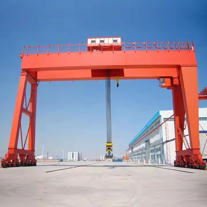
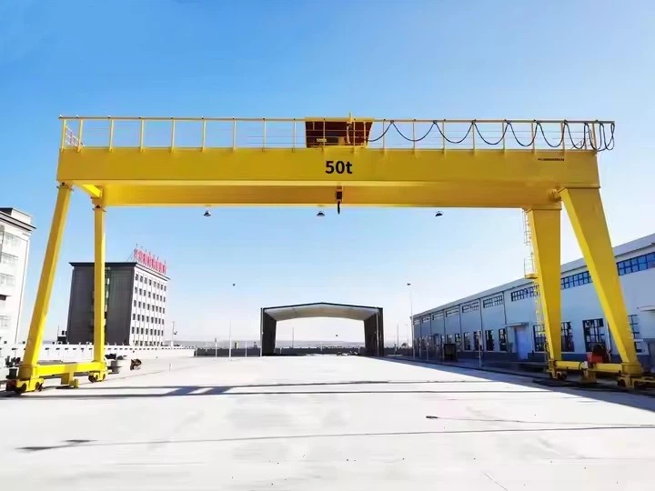
Mg Type Heavy Duty Double Girder Gantry Crane
Products Description
ADVANTAGES OF MG TYPE DESIGN
No Building Support Required: Independent ground rails make it ideal for outdoor yards, ports, and construction sites.
Extreme Load Capacity: Double girder design handles heavier loads with less deflection than single girder types.
Large Span Capability: Can span wide areas (rail lines, multiple truck lanes, stockpiles).
Customizable Lifting Attachments: Can be equipped with:
Hook: For general lifting
Grab Bucket: For bulk materials (coal, ore, grain)
Magnet: For steel plates, scrap
Rotator: For turning loads
Specialized Fixtures: For containers, coils, etc.
Reliable in Harsh Environments: Designed for dust, moisture, temperature extremes.
COMPARISON WITH OTHER GANTRY TYPES
| Feature | MG Type (Double Girder) | Single Girder Gantry | Container Gantry (RTG) |
|---|---|---|---|
| Capacity | High (5-500+ t) | Low-Medium (1-20 t) | Very High (30-100 t) |
| Span | Medium-Large (10-50m) | Small-Medium (5-30m) | Fixed (container rows) |
| Cost | Higher | Lower | Highest |
| Flexibility | High (multiple attachments) | Limited | Specialized (containers only) |
| Typical Use | General heavy industry | Workshops, light yards | Port container yards |
Lifting Capacity 320 tons
Span (Width) 3 - 12 meters (adjustable)
Lifting Height 3 - 10 meters
Working Class A3-A5 (light to medium duty)
Hoisting Speed 0.5 - 8 m/min (variable)
Main Beam Type Single/double girder (box-type)
Power Supply 220V/380V 3-phase or manual
Control Mode Pendant control/wireless remote
Hoist Type Electric chain hoist/wire rope hoist
Travel Drive Manual push or motorized
Corrosion Protection Hot-dip galvanized or marine-grade paint
Wind Resistance Up to Beaufort scale 6 (for outdoor use)
Operating Temp -20°C to +50°C

Pictures & Components
The MG (Heavy Duty Gantry) crane is a complex assembly of structural, mechanical, and electrical systems. Here is a detailed breakdown of all major components and their functions.
1. BRIDGE STRUCTURE (PRIMARY FRAME)
1.1 Main Girders (Double Beams)
Box Girder Construction: Two parallel, welded box-section steel beams forming the primary load-bearing structure.
Internal Stiffening: Longitudinal ribs and transverse diaphragms prevent buckling and minimize deflection.
Top Flange Machining: Precision-machined running surface for trolley wheels.
End Connections: Machined plates with high-strength bolt holes for connection to gantry legs.

1.2 Cross Girders (Cross Beams)
Location: Connect the two main girders at each end.
Function: Maintain girder parallelism, distribute load between girders, and provide mounting for walkways.
1.3 Walkways & Platforms
Maintenance Walkway: Full-length grating platform along one side of bridge for access.
Trolley Access Platforms: At each end for trolley maintenance.
Safety Features: Handrails (≥1m height), kick plates, anti-slip grating.

2. GANTRY LEGS & SUPPORT SYSTEM
2.1 End Trucks (Traveling Mechanisms)
Travel Wheels: 4, 8, or 16 wheels per end truck with double flanges.
Wheel Arrangement: Equally balanced bogie system for load distribution.
Axle Boxes: Heavy-duty housings with spherical roller bearings.
Wheel Material: Forged alloy steel (42CrMo), hardened to 55-60 HRC.
2.2 Rail System
Crane Rails: QU70, QU80, QU100, or P38/P43 railway profiles.
Rail Fasteners: M24/M30 high-tension bolts with elastic pads.
Rail Joints: Welded or fishplate connections with minimal gap.
Buffer Stops: Hydraulic or spring buffers at rail ends.

3. TROLLEY SYSTEM
3.1 Trolley Frame
Welded Construction: Box-section steel frame with reinforced corners.
Wheel Assemblies: 4 or 8 wheels with independent balancing beams.
Wheel Alignment: Adjustable axle boxes for precise tracking.
3.2 Trolley Drive Unit
Drive Motors: 2 x AC motors with separate brake systems.
Transmission: Hardened helical gear reducers, flexible couplings.
Synchronization: Mechanical shaft or electrical synchronization between drives.
3.3 Trolley Wheels & Rails
Wheels: Forged steel, double-flanged, Ø250-800mm.
Rails: Square steel bars (usually 50×50 to 100×100mm) or flat steel plates welded to main girder top flange.

4. HOISTING MECHANISMS
4.1 Main Hoist Assembly
Hoist Motor: AC squirrel cage or wound rotor, Class H insulation, IP55 protection.
Gear Reducer: Three-stage helical gearbox, service factor ≥1.4.
Drum Assembly:
Drum: Welded steel, grooved for rope guidance, Ø400-2000mm.
Drum Ends: Cast steel with integrated flanges and bearings.
Brake System:
Primary Brake: Hydraulic thruster or AC electromagnetic brake on high-speed shaft.
Safety Brake: Mechanical load brake on low-speed shaft (for heavy duty).
Wire Rope Reeving:
Ropes: 6x36WS+IWR or 35Wx7 construction, rotation-resistant.
Sheaves: Cast steel, precision machined grooves, anti-friction bearings.
Reeving System: 2/1, 4/1, or 6/1 falls depending on capacity.

4.2 Auxiliary Hoist
Smaller Capacity: Typically 20-25% of main hoist capacity.
Independent System: Separate motor, reducer, drum, and controls.
High Speed: Faster line speed for light loads.
4.3 Hook Block
Forged Steel Hook: Grade 80 or 100 alloy steel, safety latch.
Swivel Bearing: Thrust roller bearing for 360° rotation.
Pulley Assembly: Multiple sheaves with sealed bearings.

5. LIFTING ATTACHMENTS (INTERCHANGEABLE)
5.1 Grab Bucket System (for MG Grab Cranes)
Grab Type: Motorized (electro-hydraulic) or rope-operated (4-rope).
Capacity: 3-50 m³ volume, matching material density.
Construction:
Head Assembly: Housing with motor/mechanism and lifting lugs.
Jaws: Abrasion-resistant steel (Hardox 400/500) with replaceable teeth.
Hinge System: Oversized pins with bronze bushings.
5.2 Other Common Attachments
Electromagnet: DC rectifier with cable reel, automatic degaussing.
Container Spreader: Twistlock mechanism, telescopic frame.
Coil Lifter: Motorized rotating arms with vacuum/chuck system.
Rotator: Hydraulic or electric 360° continuous rotation.
6. ELECTRICAL SYSTEMS
6.1 Power Supply
Conductor System:
Sliding Collectors: Bronze or carbon shoes on insulated conductor bars.
Cable Reel: Motorized drum for trailing cable (for shorter travel).
Festoon System: Overhead trolley with sliding carriers.
Voltage: 380V/50Hz, 440V/60Hz, or 3.3kV for very large cranes.
6.2 Control Systems
Main Control Panel:
PLC: Siemens S7-1200/1500, Allen-Bradley CompactLogix.
VFDs: For hoist, trolley, and gantry motions (ABB, Siemens, Danfoss).
Protective Devices: Circuit breakers, overload relays, phase sequence relay.
Operator Interfaces:
Control Cabin: Insulated, air-conditioned, with panoramic windows.
Remote Control: Radio (2.4GHz) or infrared pendant with emergency stop.
Command Devices:
Master Controllers: Cam-type or electronic joystick controllers.
Push Buttons: Emergency stop, horn, light controls.
6.3 Motor Specifications
| Motion | Motor Type | Duty | Protection |
|---|---|---|---|
| Main Hoist | AC Wound Rotor or Variable Frequency | S4 40% | IP55, Class H |
| Trolley | AC Squirrel Cage | S3 25% | IP55, Class F |
| Gantry Travel | AC Squirrel Cage | S3 15% | IP56, Class F |

7. SAFETY & AUXILIARY DEVICES
7.1 Load Monitoring
Load Moment Indicator (LMI): Strain gauge sensors with display in cabin.
Overload Limit: 105% alarm, 110% cut-off (adjustable).
Anti-Two Block: For hoist upper limit protection.
7.2 Motion Limit Protection
Limit Switches:
Hoist: Rotary encoder + mechanical limit switches (up/down).
Trolley/Gantry: Cam-operated or proximity switches at travel ends.
Buffer Devices: Hydraulic or polyurethane buffers at extreme positions.
Anti-Collision: Laser or ultrasonic sensors for multiple cranes.
7.3 Environmental Protection
Anemometer: With visual/audible alarm and automatic braking.
Rail Clamps: Mechanical or hydraulic for parking in high winds.
Lighting: LED floodlights (2-4kW) for night operation.
Heating Elements: In cabin, control panels, and critical bearings.
7.4 Miscellaneous
Lubrication System: Centralized automatic grease system for bearings.
Fire Extinguisher: In cabin and main electrical panels.
Meteorological Station: Optional for temperature, humidity, wind monitoring.

8. FOUNDATION & SUPPORT INFRASTRUCTURE
8.1 Rail Track System
Rail Foundation: Reinforced concrete beams with anchor bolts.
Alignment Tolerance: ±3mm in level, ±5mm in center distance.
Expansion Joints: Allow for thermal expansion (typically 5-10mm gaps).
Electrical Insulation: Rail insulation pads to prevent stray currents.
8.2 Electrical Infrastructure
Power Column: With circuit breaker, metering, and connection points.
Lightning Protection: Surge arresters and grounding system (≤4Ω).
Earthing: Separate earthing for electrical system and structure.
9. MAINTENANCE & MONITORING COMPONENTS
9.1 Inspection Access
Ladders: Fixed vertical ladders with safety cages.
Elevating Platform: Optional for easier maintenance access.
Inspection Doors: On girder ends for internal inspection.
9.2 Monitoring Systems
Condition Monitoring (Optional):
Vibration Sensors: On motors, gearboxes, and wheel bearings.
Temperature Sensors: On brakes, bearings, and electrical panels.
Wear Sensors: On brake linings and wheel flanges.

SKETCH

Main technical

Advantages
1. Structural & Engineering Superiority
| Advantage | Technical Explanation | Practical Benefit |
|---|---|---|
| Exceptional Load Capacity | Double girder design distributes stress across two beams, allowing higher SWL (Safe Working Load) with reduced deflection (typically ≤L/800). | Can handle 5-1000+ ton loads impossible for single girder or mobile cranes. |
| Large Span Capability | Optimized box girder design with internal stiffeners maintains rigidity across 10-120m spans. | Covers entire work areas (multiple rail lines, truck lanes, stockpiles) without supports. |
| Superior Rigidity & Stability | High section modulus and torsional resistance from closed box sections. | Minimal sway during lifting/moving, crucial for precision placement of heavy loads. |
| Adaptable to Uneven Ground | Hinged leg design compensates for rail settlement up to 50mm difference. | Reliable operation on soft or settling ground where rigid structures would bind. |
2. Operational & Performance Benefits
| Advantage | Operational Impact | Economic Benefit |
|---|---|---|
| All-Weather Reliability | IP56+ electrical components, corrosion protection, wind resistance up to Beaufort 9-11. | 95%+ operational availability regardless of weather conditions. |
| High Duty Cycle | Designed for FEM M5-M8 (ISO 12482) with 1-10 million load cycles. | Suitable for 24/7 operations in steel mills, ports, and power plants. |
| Precision Handling | Variable frequency drives (VFDs) enable ±10mm positioning accuracy with anti-sway control. | Reduced product damage and safer operations in congested areas. |
| Multiple Lifting Attachments | Quick-change systems for hook, grab, magnet, spreader, rotator within minutes. | One crane performs work of multiple specialized machines. |
3. Economic & Lifecycle Advantages
Lower Lifetime Cost: 25-40 year design life with proper maintenance vs. 10-15 years for mobile equipment.
Reduced Energy Consumption: Electric operation = 40-60% lower energy cost/ton vs. diesel alternatives.
Minimal Ground Occupancy: Uses airspace, freeing ground for storage/processing (critical in ports/terminals).
Labor Efficiency: One operator handles tasks requiring 3-4 mobile machines with operators.
Automation Readiness: Easily upgraded with PLC, RFID, and positioning systems for semi/full automation.
4. Safety & Environmental Benefits
Inherently Safer Design: Separates lifting zone from ground personnel; multiple redundant safety systems.
Reduced Emissions: Zero on-site emissions (electric) vs. diesel equipment.
Noise Reduction: 70-80 dBA vs. 90-110 dBA for diesel-powered alternatives.
Spillage/Dust Control: Enclosed transfers with grab systems minimize material loss and dust.
Application
1. Ports & Maritime Terminals (Most Common Application)
| Application | Typical Configuration | Special Features |
|---|---|---|
| Container Handling | 30-100t with spreaders, 30-50m span | Anti-sway, telescopic spreader, OCR systems |
| Bulk Material Unloading | 10-40t grab, 20-35m span | Self-unloading from ships to stockpile (200-2000 TPH) |
| General Cargo | 20-200t hook, 20-40m span | Heavy lift capability for project/breakbulk cargo |
| Ship Repair | 50-300t, 30-50m span | High precision, sometimes with rotating trolley |
Case Example: Port of Shanghai uses MG gantries with 40t grabs for coal handling, achieving 1500 TPH with 2 operators vs. 6 front-end loaders with 12 operators.
2. Steel & Metals Industry
| Application | Load Type | Typical Capacity |
|---|---|---|
| Scrap Yards | Magnet or grapple | 10-30t magnet, 5-20m³ grapple |
| Slab/Bloom Handling | C-hook or vacuum | 20-50t, with rotator |
| Coil Transport | Coil lifter | 10-40t, with motorized rotation |
| Furnace Charging | Bucket or magnet | 5-15t, high duty cycle (M7-M8) |
Production Impact: Steel mills achieve 15-25% faster material flow compared to mobile equipment.
3. Power Generation
| Plant Type | Material Handled | Crane Role |
|---|---|---|
| Coal-Fired | Coal, limestone, ash | Unloading, stacking, reclaiming, blending |
| Biomass | Wood chips, pellets | Receiving, storage, feed to boilers |
| Waste-to-Energy | MSW, RDF | Pit management, feeding |
| Nuclear/Hydro | Maintenance lifts | Heavy component replacement |
Capacity Example: 2x MG cranes (32t grab) can maintain coal supply for 1000MW plant, handling 8000+ tons/day.
4. Shipbuilding & Heavy Fabrication
Component Assembly: Moving ship sections (100-800t)
Outfitting: Installing engines, propellers, deck equipment
Layout Advantage: Can span entire building dock (up to 120m)
Precision Requirement: ±5mm positioning for mating operations
5. Railway & Logistics
| Function | Configuration | Benefit |
|---|---|---|
| Wagon Loading/Unloading | Grab or magnet, 20-35m span | Covers multiple rail tracks |
| Container Transshipment | Spreader, 30-40m span | Rail-truck-container yard transfer |
| Locomotive Maintenance | Hook, 50-100t | Lifting entire locomotives for repair |
Crane production process
Phase 1: Engineering & Design (The Digital Blueprint)
This phase defines the crane's capabilities and ensures all components will function as an integrated system.
Client Specification Analysis: Engineers review detailed requirements: Capacity (e.g., 100 tons), Span (e.g., 30m), Lifting Height, Duty Class (A5-A7 for heavy cycling), and operational environment (e.g., seaport, steel mill).
Structural Finite Element Analysis (FEA): Advanced CAD/CAE software simulates stress, deflection, dynamic loading, and wind effects on the main girders, legs, and bogie frames. This ensures structural integrity under all operational scenarios.
Mobility & Steering System Design: A critical differentiator from fixed cranes. Engineers design the bogie configuration (wheel arrangement: 4x2, 8x2, etc.), steering kinematics (calculations for crab, circle, and diagonal modes), and hydraulic or electromechanical actuation.
Electrical & Control Systems Design: Creating schematics for power distribution, drive synchronization, PLC logic, and safety interlocks. Special attention is given to load sharing between multiple travel motors and steering coordination.
Bill of Materials (BOM) Generation: A comprehensive list of all raw materials and specialized purchased components.
Phase 2: Procurement of Specialized Components
RTGs require unique, high-value components not found in standard overhead cranes.
Rubber Tires & Rims: Heavy-duty, high-ply pneumatic tires (e.g., 14.00-25, 18.00-25) with specific load ratings. Often sourced from specialized industrial tire manufacturers.
Bogie & Steering Assemblies: Complete steerable bogie units, including axles, hubs, kingpins, and hydraulic steering cylinders or electric rack-and-pinion systems. May be manufactured in-house or sourced from specialized suppliers.
Power Pack: Diesel Generator Set (engine + alternator) of appropriate kW rating, or components for electric cable reel systems or hybrid/battery packs.
Specialized Drives: High-torque, low-speed travel drive motors with planetary gear reducers, often featuring integrated fail-safe brakes.
Safety & Control Electronics: Load Moment Indicator (LMI) system with sensors, anti-collision systems (laser/GPS), and steering angle sensors.
Phase 3: Heavy Steel Fabrication & Machining
A. Main Girder Fabrication
CNC Cutting: Main web and flange plates are precision-cut using CNC plasma or oxy-fuel cutting.
Sub-assembly Welding: Internal stiffeners (diaphragms) are welded to the web plates in automated welding stations.
Girder Box Assembly: The web and flanges are assembled into a box-section girder on massive, computer-controlled jigs that ensure correct camber (pre-set upward curve).
Automated Welding: Critical main seams are welded using Submerged Arc Welding (SAW) for deep penetration and superior quality. The process is often performed simultaneously on both sides to control distortion.
Stress Relieving: The complete girders undergo Vibratory Stress Relief (VSR) or thermal annealing in a large furnace to eliminate internal welding stresses.
Precision Machining: The girder ends and trolley rail mounting surfaces are machined on large planer-millers or gantry mills to ensure perfect flatness and parallelism.
B. Leg & Bogie Frame Fabrication
Legs are fabricated as welded box sections with reinforced connection points for the girders and bogies.
Bogie frames are made from extremely thick steel plate to handle massive bending moments. They are drilled and machined to precise tolerances for axle and steering component mounting.
Phase 4: Mechanical Assembly & Integration
This phase transforms fabricated parts into functional systems.
Bogie Assembly: Tires, axles, bearings, and travel drive units (motor + gearbox) are mounted onto the bogie frame. The steering mechanism (hydraulic rams or motor-driven gears) is installed and tested for free movement.
Leg-Bogie Integration: The bogies are connected to the legs. Hydraulic outrigger cylinders are installed on the legs.
Bridge Assembly: The two main girders are lifted and precisely aligned on temporary supports. They are connected by end ties and the trolley rails are bolted down with laser-leveled alignment.
Trolley Assembly: The trolley frame is built, and the main hoist (drum, motor, gearbox, sheaves) and trolley travel drives are installed. The complete trolley is then placed on the bridge rails.
Phase 5: Electrical & Hydraulic Systems Installation
Cable Tray & Conduit Installation: Extensive trays are mounted along girders and legs for power and control cables.
Drives & Control Panel Installation: VFD cabinets for all motions, the main PLC control panel, and the engine control panel (for diesel units) are mounted in protected enclosures.
Wiring & Piping: Hundreds of meters of power, control, and feedback cables are pulled and terminated. Hydraulic lines for steering and outriggers are installed, fitted, and pressure-tested.
Sensor Installation: Load cells (for the LMI), wind anemometers, limit switches, bump sensors, and steering angle encoders are fitted and connected.
Operator Interfaces: The control cabin (with joysticks, screens, and seats) is installed, or radio remote control systems are configured.
Phase 6: Surface Treatment & Painting
Abrasive Blasting: The entire structure is shot-blasted to SA 2.5 (Near-White Metal) cleanliness for optimal paint adhesion.
Multi-Coat Painting: Applied in controlled, ventilated paint booths:
Primer: Zinc-rich epoxy primer for cathodic corrosion protection.
Intermediate Coat: High-build epoxy for barrier protection.
Topcoat: Polyurethane enamel for UV resistance and color (often standard safety yellow/black).
Specialized Coatings: Undercarriage and areas prone to chemical splash may receive extra-thick or specialized coatings.
Phase 7: Pre-Delivery Factory Acceptance Testing (FAT)
Testing is more comprehensive than for fixed cranes due to the mobility systems.
Structural & Visual Inspection: Verification of all dimensions, weld quality, and assembly.
Functional Tests (No-Load):
Steering Mode Tests: Verification of all steering modes (90°, circle, diagonal, etc.).
All Motions Test: Hoisting, trolley, and gantry travel in all directions and speeds.
Outrigger Operation: Cycle testing of hydraulic stabilizers.
Load Testing:
Static Load Test: Hoist 125% of rated capacity, hold for 10+ minutes. Inspect for permanent deformation. Outriggers must be deployed.
Dynamic Load Test: Operate all motions at 110% rated capacity.
Safety System Tests:
LMI/RCL Calibration: Verify accuracy and automatic functions at multiple radii.
Anti-Collision System Test.
Emergency Stop & Limit Switch Verification.
Tilt Alarm Test (simulating unstable ground).
Phase 8: Dismantling, Preservation & Shipping
The crane is systematically dismantled into major modules: Girders, Legs (with bogies attached), Trolley, Power Pack, and Control Panels.
All exposed hydraulic ports and machined surfaces are sealed and preserved.
Components are specially crated or mounted on transport frames for ocean or heavy haulage road shipment.
Phase 9: Site Erection & Commissioning (Post-Delivery)
Foundation Check: Verification of ground bearing capacity and levelness of the operating area.
Mechanical Re-assembly: Components are reconnected using high-strength bolts.
System Re-connection: Electrical and hydraulic lines are re-connected.
Final Site Testing: Re-testing of functions, steering calibration on the actual surface, and final LMI calibration with certified test weights.

Workshop view:
The company has installed an intelligent equipment management platform, and has installed 310 sets (sets) of handling and welding robots. After the completion of the plan, there will be more than 500 sets (sets), and the equipment networking rate will reach 95%. 32 welding lines have been put into use, 50 are planned to be installed, and the automation rate of the entire product line has reached 85%.


Hot Tags: mg type heavy duty double girder gantry crane, China mg type heavy duty double girder gantry crane manufacturers, suppliers, factory
You Might Also Like


Send Inquiry